The flying attributes are like the "Psycho", which uses the same lenght leading edge. The difference is that Tim has less tendency to overspin and therefore he is able to fly more pecisely. In my opinion Tim is quite a good alternative to kites like the "Psycho" or the "Box of tricks".
This building plan is for kite builders who have some previous experience in constructing kites. Described here is all you need to know for building the kite, but not every detail.
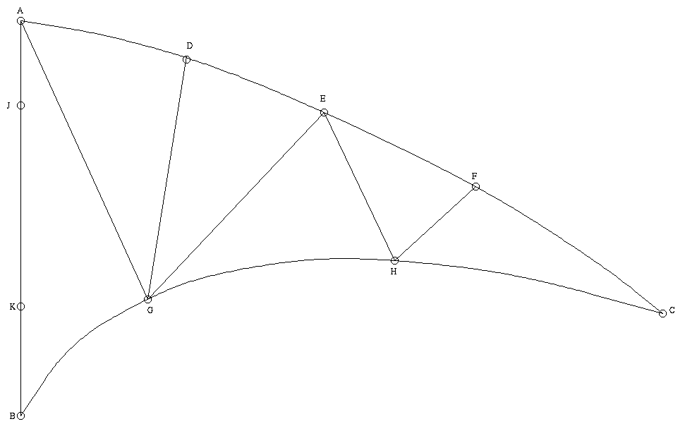
First you have to build the templates. All measurements are WITHOUT any additions for the seams.
The graphic shows a partition in the panels and the "O"'s represent the
important reference points.
Build a triangle A -> B -> C with the follwing dimensions:
The points J und K should be marked in the following distances:
Now build a right angle on the line from B to A in the point K to the right, reaching point G in a distance of 33.1 cm. Now a few right angles for the points D, E, F and H:
Now you have to build the trailing edge. You can make it with a CFG-rod too. The trailing edge has a maximum distance of 1.3 cm from the line from G to H. From the line from H to C the maximum distance is 1.3 cm also. For the trailing edge from B to G here some helpful points: Draw some right angles on the line from B to G in the distances of 10, 20 and 30 cm from B. The distances in this points are 4.6, 6.1 and 4.7 cm.
By this time you should be able to finish the templates. One more: All measurements are WITHOUT any additions for the seams.
For the sail I use Icarex P31. For the decribed partitioning I propose to use the same colour for the middle panel an the wingtip panels. To build a vented version for strong winds you can use other material like Toray or Ventex and build the panel EFH out of gauze. I have tested it - it's OK but not nessesary. A SUL version can be made out of one piece of Icarex. For the sewing I add 0.5 cm to the templates. The technique for panels that are to be sewn together is to simply lay one upon the other, fix it with a glue stick and sew the 1 cm where the nylon lies double using a sailmaker's stitch (also called a jersey stitch).
For the leading edge sleeves you can use dacron or spinnaker nylon of 5 cm. For the nose I don't use dacron and seat belt webbing, but kevlar webbing and dacron for the appearance.
The trailing edge need not to be hemmed but provided with a 1 cm wide border of spinnaker nylon. The border should end about 2 cm before point B. A tension line must be inserted into this border.
At point K you have to sew a dacron reinforcement on both sides and at point J a dacron reinforcement on the front side to avoid rub-through. The points G and H get a reinforcement on the front side for the stand-offs and point B gets a reinforcement on both sides of the following dimensions:
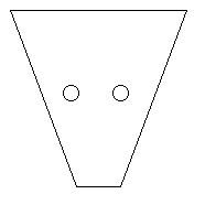
The two "O"'s shall represent the holes. The button end of the keelrod is covered by an arrow nock and should be fixed with a dacron covered rubber band. The rod is in back of the reinforcement and the rubber band goes from back to front through the left hole. Then down around the arrow nock and up through the right hole from front to back. The two ends should be knotted behind the rod. If you prefer, you can reinforce the hole with an eyelet. This all causes the sail with the reinforcement to nestle against the keelrod. The wing spars are fixed with a rubber band through a hole in the wing spar tunnel and arrow nocks. If you don't use eyelets you can try to tie the knot inside the wing spar tunnel to prevent the flying lines from becoming entangled.
For the frame you need 4 CFG-rods of a length of 1.25 m each. I use 6 mm Exel rods. 2 of the rods are used as wing spars and are used in their whole length ( I know - they stand a little far out of the tunnel). Another rod is for the upper spreader of 49.5 cm and the keelrod of 72.5 cm. The last rod is for the two parts of the lower spreader at 60.5 cm each.
If you want to save a few grams or have enough remainder you can build the upper spreader out of a 4mm rod with a 5 cm length of 6 mm-rod covering each end.
The 4 stand-offs are made out of 3mm fiberglass. I use the type that is spiral-covered. The dimensions are 2 of 20.5 cm and 2 of 14.5 cm. The short ones are placed on the first side at point H and on the second side at the lower spreader right to the fitting.
Use fittings of your own preference. I use Conflex-fittings for the spreaders, Exel center tee and arrow nocks and the same stand-off fittings like the "Stranger" ( I think they are called "Clips" and "Nops" or some such ). There is no fitting between keelrod and upper spreader!
The tension line goes from the arrow nock of one wing spar through the border of one half of the trailing edge, around the arrow nock of the keelrod and through the other half of the border to the arrow nock of the other wing spar.
Because this kite is a trick kite you should make a so-called bowline (or cheater line) too. This line connects all three arrow nocks, too, but of course doesn't go inside the borders of the trailing edge. It should have just enough tension to not hang, but not so much that it pulls the wingtips towards each other.
The bridle measures 48 cm from the pick point to the center tee, 50 cm to the fitting of the upper spreader and 55 cm to the fitting of the lower spreader.
I wish you a lot of fun building the kite. I'd like to get your (hopefully positve) feedback.
Bye mailto:Juergen_Arthofer@ms.maus.de (Please: no mails > 16 KByte)