NASA ParaWing Model 5 (NPW-5)
 or bigger.
Copyright 1995, 1996 Buck Childers
(Note: At Mel Jongen's site there is a Dutch version of this plan. Joep, Thuur & Mel have some done some nice work with the drawings to make them easier to read and details of the construction easier to understand. Even if you don't speak Dutch it may be helpful to take a look.)
Background
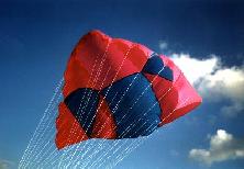
This kite is based on 1960's experimentation that NASA conducted on Francis Rogallo's parachute designs. NASA experimented with ten variations of the same basic delta shape changing the relative angle of the two keels with each model. The fifth, model 5, evidently showed the most promise for controllability and stability. The keels are formed from the row of bridle leg connections in the midsection of the sail. Some of the classic kite books that cover Rogallo show a photo of wind tunnel test being performed on model 5. I have always been intrigued by the form.
In 1995 Chuck VanEekelen, a kite flyer in the Netherlands, sent me a Dutch plan, containing basic dimensions and bridling information, necessary to turn Model 5 into a controllable kite. Chuck and I worked through our first couple of these together shared construction tips and improvement suggestions via e-mail along the way. The following plan is my representation of the kite and how to build it.
---Added May 1996---
In April 1996 I ran across Mel Jongen's www page that had a Dutch version of this plan. As
it turns out Mel was the person that provided Chuck with the plan just before Chuck and I
got together. Mel's version is available at his site. His bridle measurements
for A11, A12, and B6 had been optimized and I've included those changes in my tables.
(Thanks Mel)
---
Description
Model 5 is a single skinned, sparless, parawing. It is meant for traction, (ie. It Pulls!). Mine is usually dual line although it can easily be set up for quad. It turns quick but it's forward speed is relatively slow. It has a moderately narrow power zone. I've buggied with it but it really doesn't have edge characteristics that make a useable buggy engine. Darts are sewn in the nose area to create a significant camber which is maintained through air pressure and the bridle structure. The standard version has a sail area of 3m^2 (about 30sq ft). The kite can easily be scaled from .7m^2, which makes a nice toy, to over 7m^2 which could be quite dangerous. Even in the 3m^2 version it has a tendency not to want to land.
Building
All measurements needed are calculated based on the keel length you pick as a starting point. If you like inches use inches if you like cm. use cm. I prefer metric so the example given is based on a 2 meter keel length providing a sail area of 3 meters (about 30 ft^2).
Materials
- ¾ oz ripstop - 3+ m^2 (nylon)
- 80 lb dacron - 12m (reinforcement)
- 50 lb dacron - 38m (bridle legs)
- peel -n- stick nylon (reinforcement)
Standard procedure
The drawings show threee main panels; one center and two wing panels. Add your favorite
seam and hem allowance where appropriate. I prefer to use a 1cm French seam where the wing
panels attach to the center panel and creating a 1cm hem by folding a 2cm strip around the
edge and sewing it on. This creates a tunnel to thread the dacron line for reinforcement.
- Cut or build up sail panels (Based on the size being built you may or may not have to piece together for these panels.)
- Sew wing panels to center panel
- Mark where darts are to be added to nose (indicated with grey triangles)
- Mark all bridle and tie down attachment points
- Sew darts
- Hem entire edge
Reinforcements
Add reinforcements AFTER the sail is seamed, darted and hemmed. You should have marked
bridle attachment points and seven (7) tie down points prior to darting nose.
- Use a needle to thread the 80lb dacron line through the tunnel created by the center/wing panel seams.
Affix the line by sewing through it along the length of the seam.
- Thread dacron line through the tunnel created by the hem.
- Affix the line around the edge of the sail (as close to the edge as possible.)
- Cut out "1 pieces of peel-n-stick nylon and stick to both sides of the sail at the attachment points where the tie down lines support the nose shape. (This nylon could also be sewn in place)
- Add the tie down lines (length K) to create the nose shape (see figure) along the front edge of the sail.
Bridle attachment
The bridle lengths are provided in the table below. I use the following technique to
attach bridle legs. It allows me to remove the entire bridle or make adjustments to
individual bridle legs with relative ease.
- Cut 36 pieces of dacron about 10 cm each
- With a needle, thread each piece of dacron through the sail at the attachment point, around the dacron reinforcement, and back. Tie a secure slip knot, trim and melt the line at the knot so it doesn't unravel. (you should now have 7-8 cm of loose line hanging from the attachment point)
- Starting about 1cm from the sail tie about 4 overhand knots in the line 1cm apart.
- Make the individual bridle legs based on the lengths (including overhand loops at each end) needed in the Bridle Leg Table.
- Larks head each bridle leg to its respective line at the attachment point on the sail. I start with the second knot from the sail.
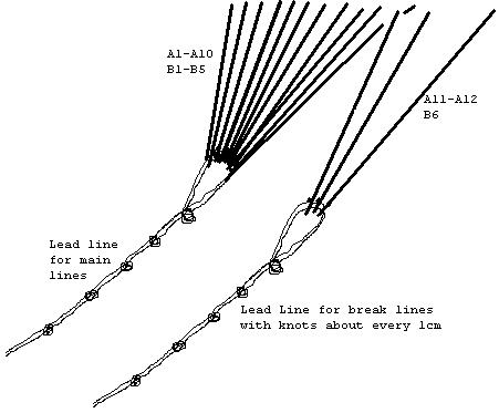
- Bring together all the bridle legs on the right side to a single tow point
Bring together all the bridle legs on the left side to a single tow point
Adjustments
Dual line
Each individual bridle leg is adjustable. Every change has an affect on the
characteristics of the sail and a little experimentation will allow you to maximize
performance. When tuned the kite should have good forward movement without
"lurching". Lurching usually indicates that the sail is too flat, lengthen lines
in the A3-A4 area. Changing the tie lines that keep the nose shape will also change the
flight characteristics.
In dual line flight the most common adjustments are for different wind speeds. In lower winds A11, A12, and B6 by a few centimeters. In higher wind lengthen them. This process is simplified by bringing together these lines to their own towpoint and making the adjustment at the towpoint..
Quad
Quading is accomplished by bringing together bridle legs A11, A12, and B6 together in a
single towpoint and using this as the break line. In quad line flight you basically have
the ability to make the dual line adjustments variable.
Figures
Sail Template
Bridle Leg Table
Bridle |
Factor |
Length for kl=2 (cm) |
A1 |
0.975 |
195.0 |
A2 |
0.990 |
198.0 |
A3 |
0.985 |
197.0 |
A4 |
0.975 |
195.0 |
A5 |
0.980 |
196.0 |
A6 |
0.975 |
195.0 |
A7 |
0.985 |
197.0 |
A8 |
0.970 |
194.0 |
A9 |
0.960 |
192.0 |
A10 |
0.955 |
191.0 |
A11 |
0.925 |
185.0 |
A12 |
0.870 |
174.0 |
B1 |
0.930 |
186.0 |
B2 |
0.910 |
182.0 |
B3 |
0.875 |
175.0 |
B4 |
0.850 |
170.0 |
B5 |
0.775 |
155.0 |
B6 |
0.700 |
140.0 |
Detail of Nose
Measure |
Factor |
Length for kl=2 (cm) |
A |
0.054 |
10.8 |
B |
0.063 |
12.6 |
C |
0.200 |
40.0 |
D |
0.066 |
13.2 |
E |
0.017 |
3.4 |
F |
0.080 |
16.0 |
G |
0.040 |
8.0 |
H |
0.026 |
5.2 |
I |
0.096 |
19.2 |
J |
0.020 |
4.0 |
K |
0.026 |
5.2 |
If you build from these plans please let me know. I would like to hear from people about experiences with the kite and suggestions for improvement to the plans.
Buck Childers mailto:buckchil@sound.net
P E A C E