|
|
|
|
|
|
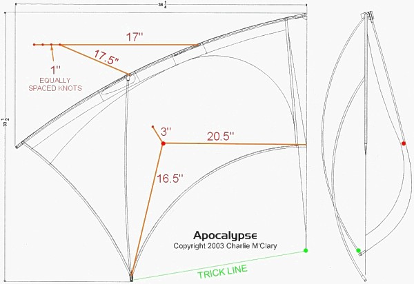
About the Apocalypse These plans are published with the permission of Charlie M’Clary to share his design with amateur builders. Besides appearance, the Apocalypse is an unusual kite for having a drum-tight sail, a central stabilizing keel and no straight spars. The sail tension is increased by the perimeter leech lines and bowed spars that keep the entire sail tight and responsive. Unlike other quad line kites, a central keel provides directional stability. To aid assembly, storage and transportation, the LE spars disconnect from the nose fitting for disassembly, keeping the spars with connectors and bridle knots intact. Openings for the LE fittings and slots for the bridle allow limited movement of the spars. A Dacron and Velcro flap retains the nose fitting. The kite is 33.25 inches (850 cm) high and 79.5 inches (201.9 cm) wide, weighing 6.4 ounces (182 grams). Charlie says it doesn't dead-launch easily, but he seems to like how it tricks on slack lines.
|
|
 |
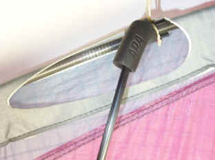
Rear of nose The nose fitting drilled to accept a .125” carbon rod. This holds a ferrule bent to the angle of the leading edge spars. Velcro serves to fasten the Dacron flaps that allow easier disassembly. Icarex PC covers the white flaps in the photo |
|
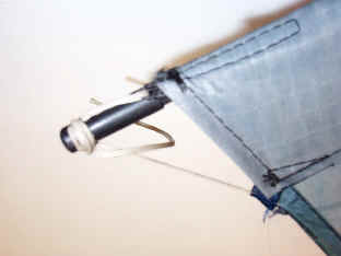
Rear of leading edge A standard APA sport kite leading
edge fitting and c-clip hold the .180” pultruded carbon vertical spar.
The Dacron-reinforced oval hole allows disassembly by sliding spar from
nose fitting. The vertical spars all arch away from the sail, leaving it
flat.
|
|
 |
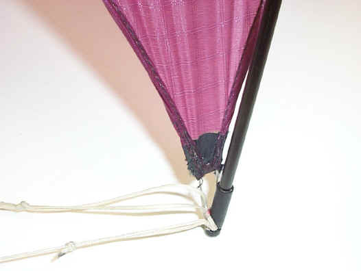
Rear of leading edge This is one of the upper bridle points that are through a slot to allow movement of the SkyShark 3PT leading edge spar.
|
|
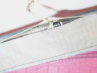
Rear of wingtip Tiny folded strips of Dacron form
loops to tie tensioning lines for LE and leech lines. 75 pound Braided
Dacron line is used for all tension lines. The FSD nocks have a side notch to
tie to. The leech line goes through the nock, back to the wingtip loop
and back to the nock to be tensioned and tied. |
|
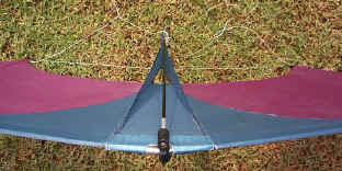 |
Looking down the center front The
.180” carbon keel spar is shown as it supports the keel. At its lower
end a .098 carbon rod is spliced to form the curve of the lower keel. |
|
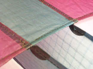
Center of trailing edge The intersection of the keel and
trailing edge is shown here. The black circular reinforcements are of
pressure sensitive ¾ ounce rip-stop tape applied prior to stitching. |
|
 |
The lower end of wing vertical spar Here again the leech lines run through the nock, and lower trick line and bridles lines attach to the wing spar nocks. |
|
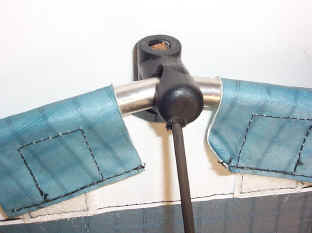
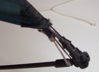
The lower tip of the keel This is the connector at the keel tip where the rear spar joins it at about 60 degrees. The rear spar on the bottom has a sleeve to stop it against the fitting, The fitting is actually a T-fitting for drip irrigation tubing with two barbs removed. This could be accomplished with .098 leading edge fittings such as those used on the Prism Micron. The lanyard to the fitting tensions the fabric. |
|
The bridle tow points can be made with adjustable knots for lateral adjustment if desired. |
|
|
Leading edge spars
(2) SkyShark 3PT 38.5" long
|
|
| Apocalypse plan downloads | |
|
The template drawings are downloadable in a zipped file that includes full-scale CDR, AI and DXF drawing files. |
Template drawings are also downloadable in a full-scale JPG file for builders without a drawing program. |
| A JPG file showing an assembled kite is available. | Feel free to ask questions. I
haven't made one yet, but plan to. -Stan |